The Critical Role of Control Cables in Automation
Industrial automation systems depend on reliable signal transmission between sensors, controllers, and actuators. Unlike power cables that simply deliver electrical energy, control cables carry information—position feedback, temperature measurements, status signals, and command communications. Signal integrity in these cables directly determines system reliability and performance.
A single automation system may incorporate hundreds of control cable runs connecting distributed I/O modules, variable frequency drives, motor starters, process instruments, and central control systems. Each cable represents a potential failure point; cumulative failure probability across hundreds of cables demands exceptional individual cable reliability.
Control cable failures create multiple symptom categories: intermittent communication causing unpredictable system behavior, complete signal loss stopping automated processes, and signal corruption introducing measurement errors that propagate through control algorithms. All these failure modes reduce productivity, increase debugging time, and may create safety concerns.
Modern automation systems operate at increasingly higher speeds and lower signal levels. Ethernet-based fieldbus systems, high-resolution analog signals, and fast digital communications demand cable performance that earlier-generation control cables cannot provide. Understanding application requirements enables appropriate cable selection.
Understanding Control Cable Construction
Conductor Configurations
Control cables employ various conductor configurations matched to specific applications. Multi-conductor cables with individually insulated conductors serve discrete signal and control circuits. Paired constructions with twisted conductor pairs provide balanced signal transmission superior to parallel conductor arrangements.
Twisted pairs cancel electromagnetic interference through differential signaling. The equal and opposite voltages induced in each conductor of a twisted pair cancel at the receiver, rejecting common-mode noise while preserving the differential signal. Twisting pitch (turns per meter) influences noise rejection effectiveness—tighter twists provide better high-frequency performance.
Triad configurations serve three-wire resistance temperature detector (RTD) circuits and certain measurement applications requiring three connections. The three conductors carry excitation current and measure voltage drop across the sensor element.
Shielding Strategies
Shielding protects signal conductors from external electromagnetic interference (EMI) while preventing cable emissions from coupling into nearby sensitive circuits. Multiple shielding approaches suit different interference environments and performance requirements.
Overall foil shields encircle all conductors within a cable, providing comprehensive protection against external interference. Aluminum-polyester foil shields are lightweight and cost-effective, though mechanically fragile. Copper-backed foils offer improved durability while maintaining shielding effectiveness.
Braid shields provide mechanical protection and improved shielding coverage compared to foils, particularly at higher frequencies. Copper or tinned copper braids offer 60-95% coverage depending on braid construction. Combining foil and braid shields provides comprehensive protection for the most demanding environments.
Individual pair shielding isolates each signal pair from crosstalk with adjacent pairs. This construction suits multi-pair cables carrying multiple high-speed signals where inter-pair interference threatens signal integrity.
Matching Cable to Application
Digital Signal Applications
Discrete digital signals—on/off status, contact closures, and binary commands—tolerate moderate noise levels but benefit from twisted pair construction that rejects interference. Shielding requirements depend on installation environment; benign office-type conditions may permit unshielded cables, while industrial environments with motor drives and switching power supplies typically require shielding.
Cable length influences signal integrity for digital signals. Standard digital logic handles relatively short runs; longer distances may require special line drivers, termination networks, or selection of cables designed for extended digital transmission.
Analog Signal Applications
Analog signal cables demand higher performance than discrete digital cables due to their lower signal levels and higher accuracy requirements. A 4-20mA current loop—the industry workhorse for analog transmission—requires cables that maintain signal accuracy despite electrical noise.
Thermocouple extension cables must match the specific thermocouple type (J, K, T, E, etc.) and maintain accuracy over long distances. Using incorrect extension cable types introduces measurement errors that increase with cable length.
RTD measurement cables require three conductors of matched resistance for accurate three-wire measurements or four conductors for four-wire configurations. Resistance mismatches between measurement conductors introduce systematic errors.
Communication Bus Applications
Fieldbus and industrial Ethernet cables represent specialized categories with specific performance requirements. PROFIBUS, DeviceNet, Foundation Fieldbus, and various industrial Ethernet variants (PROFINET, EtherCAT, EtherNet/IP) each define specific cable requirements.
These communication cables undergo standardized testing to verify characteristic impedance, transmission delay, and crosstalk performance. Using cables not meeting specification can cause communication errors, reduced data rates, or complete system failure. Always specify cables matching the exact communication protocol requirements.
Installation Best Practices
Routing Considerations
Control cable routing significantly influences system reliability. Maintain minimum separation from power cables—typically 15-30cm for parallel runs, increasing with power cable voltage and current. Where crossing power cables, cross at right angles to minimize coupling area.
Avoid routing control cables near variable frequency drives, welding equipment, or other high-frequency noise sources. When unavoidable proximity exists, additional shielding or physical separation becomes essential.
Keep cable runs as short as practical. Long cable runs increase susceptibility to interference and voltage drop. When long runs are necessary, select cables with larger conductor sizes or signal conditioners to maintain signal quality.
Mechanical Protection
Protect control cables from mechanical damage through appropriate installation methods. Cable trays provide organized routing while protecting cables from external damage. Conduit offers superior protection for runs exposed to physical contact or potential impact.
Support cables adequately to prevent excessive sag or tension. Cable ties should be snug but not compressive—over-tightened ties deform cable jackets and may damage internal construction. Use appropriate tie materials for the environment; UV-resistant ties suit outdoor installations.
Grounding and Shield Termination
Shield grounding requires careful attention. Shields should ground at one end only for most applications, preventing ground loops that introduce noise. The grounded end should connect to the system ground at the source equipment (receiving equipment for signal cables, driving equipment for output cables).
Drain wires facilitate shield termination while maintaining flexibility. Solder connections or crimped terminals provide reliable terminations. Pigtail shield connections—twisting shield braid into a pigtail—create stress concentrations and inconsistent contact; compression-style shield terminations provide superior reliability.
Environmental Protection
Environmental conditions influence cable selection and installation practices. Outdoor installations require UV-resistant jackets that resist sunlight degradation. Underground runs need moisture-resistant constructions or conduit protection.
Temperature extremes may require special cable compounds. Cold temperatures make cables brittle and difficult to install; specialized cold-rated cables maintain flexibility at low temperatures. High-temperature environments require cables rated for continuous operation above ambient temperatures.
Chemical exposure from oils, solvents, or corrosive substances may attack standard cable materials. Identify specific chemicals present and select cables with compatible jacket compounds.
Maintenance and Troubleshooting
Regular inspection identifies developing problems before they cause system failures. Visual inspection should check for jacket damage, secure terminations, and proper grounding connections. Thermal imaging during system operation identifies hot spots indicating loose connections or overcurrent conditions.
Maintaining documentation simplifies troubleshooting when problems arise. Record cable identification, termination points, and as-built routing. Update documentation when modifications occur; undocumented changes create future confusion.
When troubleshooting control system problems, systematic isolation helps identify fault locations. Temporary bypass of suspected cable segments, substituting known-good cables, and cross-referencing with functioning similar circuits all narrow search areas.
Conclusion
Control cables form the nervous system of industrial automation, carrying information that determines system behavior. Appropriate cable selection matched to application requirements—considering signal type, bandwidth, interference environment, and installation conditions—ensures reliable signal transmission throughout system life.
Installation practices compound the importance of cable selection. Proper routing, termination, grounding, and environmental protection maximize the value of selected cables while preventing premature failure.
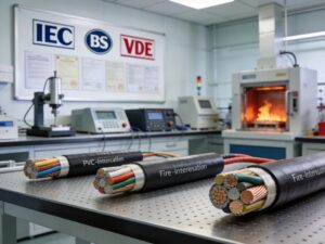
Jinyi Cable Co., Ltd. manufactures comprehensive control cable product lines including shielded, unshielded, and bus communication cables. Our technical team supports industrial automation projects worldwide with cables meeting IEC and international standards.